![]() CLICK HERE TO DONATE TO HELP FUND THIS SITE!
CLICK HERE TO DONATE TO HELP FUND THIS SITE!
NEW CLICK HERE TO SEND US A GIFT! A COOL IDEA TO HELP US FOR HELPING YOU!
NEW CLICK HERE FOR THE AMAZON PRIME PAGES!
NEW CLICK HERE FOR HOLIDAY CARDS AND WRAPPING PAGES
NEW CLICK HERE FOR THE UPS PAGES
NEW CLICK HERE FOR HOME AUTOMATION PAGES ALEXA AND FIRE TV AND GOOGLE HOME ITEMS
NEW CLICK HERE FOR Y 3 K PAGES
NEW CLICK HERE FOR THE HOUR METER PAGE
CLICK HERE FOR THE FITTINGS ID PAGES FOR HOSES AND PORTS
NEW CLICK HERE FOR HYD ORINGS PAGES
CLICK HERE FOR THE BIG SHOP TOOLS PAGES
CLICK HERE FOR THE LISLE TOOLS PAGE
CLICK HERE FOR THE THREAD SIZE PAGE
CLICK HERE FOR THE BOLT TORQUE PAGE
CLICK HERE FOR CONSTRUCTION PAGES
CLICK HERE FOR THE WIND POWER PAGES
CLICK HERE FOR HEALTH CARE PAGES
CLICK HERE FOR TV ANTENNA AND ROTOR PAGES
CLICK HERE FOR THE ELECTRONICS PAGES
CLICK HERE FOR THE SAFETY PAGES
NEW CLICK HERE FOR LOCKS PAGES
CLICK HERE FOR IPAD IPHONE PAGES
CLICK HERE FOR THE TRACK AND TELL PAGES
CLICK HERE FOR WORK CLOTHING PAGES
CLICK HERE FOR THE LITHIUM RECHARGEABLE BATTERY PAGES
CLICK HERE FOR THE EMERGENCY LIGHTS PAGES
CLICK HERE FOR THE BELT ALIGNMENT PAGES
CLICK HERE FOR THE HVAC AIR CONDITIONER PAGES
NEW CLICK HERE FOR THE HOT WATER HEATER PAGES WITH RECIRCULATION PUMPS
CLICK HERE FOR THE WINDOW TINT PAGE WITH BLACK OUT TINT TOO!
CLICK HERE FOR THE CAMPER TRAILER LIGHTS WIRING DIAGRAM PAGE
NEW CLICK HERE FOR THE DIESEL REPAIR PAGES
IECO 210 HP 4 CYL / POUSTUSA CHEVY VEGA PAGE
RADIO SERVICE RADIO CONVERSION AND MORE
SALVAGE YARD LINKS STATE BY STATE LISTINGS
CLICK HERE FOR EQUIPMENT AND SMALL ENGINE PAGES WITH LINKS HONDA PAGES TOO AND HOW TO!!
CLICK HERE FOR THE MOUSE TRAP PAGES A TRAP THAT WORKS FOR US!!
CLICK BELOW FOR THE COOL UNIT CONVERTER SITE
CLICK HERE FOR SHOP TOOLS AND EQUIPMENT PAGES
CLICK HERE FOR MUST HAVE TOOLS LIST PAGE
CLICK HERE FOR AIRCON SOFT START PAGES
CLICK HERE FOR THE INVERTER WINDOW AC UNITS
CLICK HERE FOR THE ELECTRICAL TOOLS AND PARTS PAGES AND MORE!
NEW CLICK HERE FOR RESTAURANT PAGES
NEW CLICK HERE FOR TRUCK CRAIN BED LIFTS
CLICK HERE FOR THE POWER WASHER PAGES
CLICK HERE FOR THE DRAINZIT OIL DRAIN PAGES
CLICK HERE FOR THE DC FUSE PAGE ATO, ATC, MAXI, GMA
 Note:
Spacers not normally recommended.
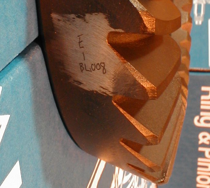 ,
which means a backlash figure of .008 inch at the closest point.
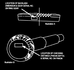
Pinion depth settings (or checking distance) are marked on the face of the
pinion gear as follows (see illustration B): Ref: CD 2.799,
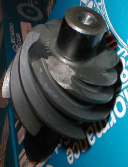
which means distance of 2.799 inches from centerline of the ring gear to pinion face. Dimensional variations for backlash SHOULD NOT EXCEED .004" variation.


Properly designed, manufactured, and maintained Richmond Gears, correctly assembled by you in a clean, rigid gear box, and operated with the proper lubricant, should result in safe and satisfactory performance. Be sure you select the proper application for your gear set.
A new ring and pinion installation, especially a high numeric ratio with new bearings, can cause an excessive heat buildup in the rear end and cause softening of the gear teeth and bearings if a break in is not performed.
Street vehicles should be driven at normal street driving speed for approximately 10 miles, then stop and let cool for 30 minutes. Do this 2 to 3 times. Towing vehicles need approximately 200-300 miles of normal street driving before being used for towing.
On circle track race cars make approximately 6 to 8 laps at slow speed, then let cool for 30 minutes. Make 6 to 8 more laps at slow speed, then 2 to 3 laps at full speed, the let cool again for 30 minutes.
Drag cars need only an initial run-in since they are driven short distances and heat is not normally a problem with proper lube and backlash allowance.
NOTE: If after the above break in is performed, overheating of the rear end is suspected, repeat the final portion of the break in procedures.
HELPFUL HINTS & ADDITIONS TO RICHMOND GEAR INSTALLATION INSTRUCTIONS
After completely reading instructions, go back to Step #4. The following group
of shim thickness are only if you do not have access to a pinion depth gauge or
the old shim from the old pinion to start with. GM - .035", Ford 8"-9" - .020",
Ford 8.8"-7.5" - .030", All Dana's - .035", 8 3/4" x 1 3/4" pin, - .090", 8 3/4"
x 1 7/8" pin, - .020", Mopar - 9 1/4" - .020"
Pinion depth shims are located underneath the rear pinion bearing cone that is
pressed on pinion with exception of the Dana Models. Dana pinion depth shims are
underneath the rear pinion bearing cup in the housing. Dana carrier bearing
pre-load shims are between carrier and bearing cone. All others are on the
outside of bearing cup unless spanners are used as in the Ford 8 and 9 inch,
both 8 3/4 and Mopar 9 1/4. Ford 8 and 9 inch pinion depth is regulated by shims
between pinion support and chuck or center section.
Step #5 - If crush collar is used to set bearing
pre-load, do not use until you have established pinion depth and backlash and
you are satisfied with the pattern you get. You can simulate pinion bearing
pre-load by tightening pinion nut until the right pre-load is achieved with only
motor oil on the pinion bearings. The crush collar and pinion seal should be
last to install.
Step #7 - GM rear cover style housings use shims on
the outside, between bearing cup and housing, adjusting backlash and carrier
bearing pre-load If starting with a bare housing, or you are installing a spool
or different carrier, before you mount the ring gear, establish equal shim pack
on each side of carrier and enough to create a drag when you slide it in and out
of the housing by hand. Keep in mind you should keep the thickest shim next to
the bearing cup. With a little loctite on the threads of the rings gear bolt,
mount gear to carrier or spool. After adjusting shim pack to get proper backlash
and once you have established your pattern, remove carrier and pinion. Now is
the time to install crush collar and pinion seal. NOTE" Always use loctite on
the pinion nut. If you do not have a rear end housing spreader, you will have to
work at installing the carrier once you add more shim to pre-load the carrier
bearings. As a rule of thumb all carrier bearings will require .010 pre-load
After adding .005 to each side of the shim pack, coat surfaces of the shims with
axle bearing grease to hold them in the housing, make sure the cups stay
straight. Using a plastic or brass hammer, gently pound on bearing cups side to
side until carrier has seated in housing. Again, it is important that you keep
the cups straight during this operation. A spreader is almost necessary for all
Dana Model rear ends. Torque caps to proper torque value.
LOGO'S














![[Most Recent Quotes from www.kitco.com]](http://kitconet.com/images/quotes_7a.gif)